| |
| |
 |
PRODUCTS
CENTER |
 |
| |
Centrifugal
Ventilator
Ⅰ、Classification
of Centrifugal Ventilator
1.Classified according to the pressure
(1)Low pressure centrifugal ventilator―wind pressure≤980Pa
(2)Medium pressure centrifugal ventilator―wind pressure980-2942Pa
(3)High pressure centrifugal ventilator―wind pressure2942-14710Pa
2.Classified according
to the purpose
(1)General purpose centrifugal ventilator―used for the ventilation
of building and the blast of industrial stove,suchas 4-72,4-79,6-23,6-30,9-19,9-26
(2)Dustremoving centrifugal ventilator―used for removing the dusty
air like grinding wheel scraps,saw sawdust,paring,energy feeding,etc.,such
as C6-48 and C4-73 series.
(3)Coal powder centrifugal ventilator―used for feeding coal powder
in the thermo power plant,such as M7-29 and M9-26 series,etc.
(4)Boiler centrifugal blower―used for blast and smoke removalin
the thermo power station and other steam boiler;blastrefers to ventilator,and
smoke removal refers to blower,such as G4-73,Y4-73,Y5-47,Y5-48,GG2-10,GY2-10
series,etc.
(5)Mine centrifugal ventilator―used for the mine ventilation,of
nearly the same structure with the general purpose large―scale centrifugal
blower.Due to the mine work condition,the ventilator is mostly exsuction
type,therefore air income cabin and throttle device are installed
to the entrance and exit of the ventilator or blower.
(6)Antisepsis centrifugal ventilator―used for removing the corrosive
gas.According to the or der requirement,acid-proofpaint or rubber
liner is added to the general purpose ventilator or blower.
(7)Blast centrifugal ventilator―used for removing the flammable
and explosive gas.With aluminum as the impeller material for this
kind of ventilator or blower.
(8)High temperature centrifugal ventilator―used for removing the
gas of the temperature above 250℃,mainly used in the industries as
metallurgy,power station,chemical,etc.
(9)Ventilator of other purpose-specially designed ventilator for
specific purpose. |
Ⅱ、The
full title of the centrifugal ventilator includes:
Name,model,engine number,transmission mode,revolving direction,windhole,altogether
sixparts.
1.Model consists of basic model and supplementary model,in three
groups,separated with dashmark.The basic model covers the first two
groups,referred with the expression of the full pressure coefficient
at the highest efficiency point of the ventilator or blower multiplying
10,in integral and the ratio revolution.The supplementary model covers
the last group,expressed with the model code of the ventilator or
blower(Fig.1)and design number.
In order to differentiate the ventilator or blower in the same basic
model and with different purpose,purpose code may be added before
the basic model(Fig.2) |
Fig.1
| Code |
0 |
1 |
2 |
| Entrance type |
both-side inhalation |
single-side inhalation |
two-level inhalation in series |
|
Fig.2
| Purpose classification |
Code |
Purpose classification
|
Code |
| Chinese
character |
Abbr. |
Chinese character
|
Abbr. |
| Gener al purpose ventilation |
General |
T |
Coal power feeding |
Coal power |
M |
| Blast gas ventilation |
Blast |
B |
Grain powder feeding |
Powder |
FM |
| Anticorrosive gas ventilation |
Anticorrosive |
F |
Hot wind feeding |
Hot wind |
R |
| Industrial cooling water ventilation |
Cooling |
L |
High temper ature gas feeding |
High temper ature |
W |
| Mini electric blow |
Electric |
DD |
Sinter smoke |
Sinter |
SJ |
| Ship ventilation |
Ship |
CT |
Air power |
Power |
DL |
| Textile industry ventilation |
Textile |
FZ |
Blast fur nace blast |
Blast furnace |
GL |
| Mine body ventilation |
Mine |
K |
Converter blast |
Converter |
ZL |
| Tunnel ventilation |
Tunnel |
SD |
Coal gas blast |
Coal gas |
MQ |
| Boiler |
Boiler |
G |
Chemical gas feeding |
Chemical gas |
HQ |
| Ship boiler ventilation |
Ship boiler |
CG |
Gas feeding in petrolrefinery |
Petrol gas |
YQ |
| Ship boiler blow |
Ship blow |
CY |
Natural gas feeding |
Weather |
TQ |
| Industrial boiler ventilation |
Industrial |
GY |
For cooling wind |
Cooling wind |
LF |
| Boiler blow |
Boiler blow |
Y |
Refrigeration |
Refrigeration |
LD |
| Dustremoval ventilation |
Dustremoval |
C |
Air conditioning |
Air conditioning |
KT |
|
2.Engine number
The outside diameter of the impeller is expressed with decimeter(dm.)
3. Transmission mode
Specified in six model as stipulated in
Fig.3
| Code |
A |
B |
C |
D |
E |
F |
| Transmission
mode |
Direct
transmission
of motor |
Cantilever
supporting strap
wheel is amidst the
bearings |
Cantilever
supporting strap
wheel is amidst the
bearings |
Cantilever
supporting shaft
transmission |
Double
supporting
strap
transmission |
Double
supporting
shaft
transmission |
4. The blower rotates in left and right directions as:facing the
impeller,clock wise is right,contrarily left.
5.The wind hole dire tion is gener ally made 90 degrees.For customer's
special requirement,specify in the order(See Figure1 for various
wind hole angles)
Facing form one end of the blower to get the following
view
 |
Ⅲ、Example
of full title:boiler centrifugal ventilator G4-73-11No.10D right 90°
 |
Ⅳ、Notice
for the selecting of ventilat or perfor mance
1.The project design and user shall select the ventilat or model
according to the location and environ ment,and then decide the ventilat
or number and motor power from the performance according to the flow
and full pressure.Besides the motors stipulated in the in in the performance
chart,other motors also may be selected,and specified clearly in the
order. 2.The performance of each rotating speed is the performance
chart within the range of 90% at the highest efficiency point,to
be divided into 4 to 8performance points.The performance chart shall
prevail in or dering.
3.The qualified performance of the ventilator or blower at delivery
is that the full pressure value in not exceeding-8% under the given
flux.
4.Parameter supplied in the performance chart,if no other explanation,is
gener ally calculated at the air medium of gas temper ature t=20℃,air
pressure P=101325Pa,air weight degree γ=1.2kgf/m3(1kgf=9.8N)
5.Motor power needed in every work condition point in the performance
chart:
 in the formula: in the formula:
Q------flux(m3/h)
N------motor power(kw)
P------full pressure(mmH2O)
η-----full pressure efficiency
ηm----mechanic efficiency is 1 in “A”type and 0.96 in “C”type.
K------Safety factor of motor capacity:k=1.2 for 2-5kw,and k=1.15
for more than 5kw.
6.The attached performance parameter chart is the performance
parameter of the blower at certain rotating speed and under the
normal status.If the rotating speed,impeller diameter or gas density
get changed,then the conversion formula of the performance parameter
is as follows:
|
Ⅴ、Installation,Debugging
and Running:
1 Before the installation,all parts of the ventilator must be checked
thoroughly,the rotation direction of impeller and hull should be same,all
connections should be steady and no friction exists when the impeller
is rotating,any found questions must be resolved immediately. 2
The following items should be checked before installation:No tools
or sundries can be left in the hull,the connection between outlet
and inlet pipe should be coupled naturally,and connecting by force
is not allowed.It is forbidden to add the weight of pipe to the
ventilator,and the levelness of the ventilator's main shaft should
be checked also.
3 As for axis jointer or blower with transmission,examine whether
the axis jointer,strap wheel or the strap is installed reliably.The
positions of the two strap wheels are in one central line;whether
the concentric degree between the blower axis and the motor axis
meets the technical requirement(radial displacement 0.1mm,gradient
0.8/1000).
4 Have a test run after the ventilator has been installed,start
the ventilator under the zero-load status,that means the inlet adjusting
valve should be closed,and the outlet valve opens a little,the working
current should be inspected carefully during the starting process
and can't exceed rated value,if the ventilator runs well,open the
valve to normal operation status gradually.
5 After the speed reaches the normal value,the bearing temperature
should be checked(under 80℃ in normal condition),it any abnormal
phenomena appear,such as serious vibration,high bearing temperature,abnormal
|
Ⅵ、Maintenance:
1 In order to avoid the fault or accident caused byabnormal usage
and extend ventilator's service life,the maintenance and check must
be strengthened.
2 Filter device or dust-remover should be mounted in front of the
inlet,if no devices mounted on the inlet,shield nets is needed to
avoid something sucked in and damage the impellor
3 Remove dust or dirt in the ventilator and the pipe regularly.
4 Add or change lubrication grease regularly.
5 Examine and repair according to the following trouble:
a)The blower vibrates violently
1.The base rigidity is inadequate or not firm
2.The wind hole and the impeller scrub
3.Loose connection between parts or ground bolt
4.Loose of impeller rivet or distortion of impeller
5.Bad installation of wind hole,causing resonance
6.Vane begrime,abrasion,distortion of impeller,axis bending cause
unbalance to rotor.
7.Poor installation of strap wheel,motor axis is not concentric
to blower axis.
b)Exorbitant bearing temperature
1.Disabled lubricant or with impurity as dust or sand
2.Too fast or loose of the bearing base or connecting bolt
3.Damaged ball bearing
c)Excessive current
1.Excessive gas density causes the motor overload.
2.Low voltage or single-phase power disconnection.
|
Ⅶ、Special
Warning:
1.After finishing the installation of blower,make stable grounding
of the motor.
2.Close tightly the wind hole before each start.Open the wind hole
after normal running.
3.No sundries entering the blower during the runni.
|
| 1 [2] [3] [4] [5] [6]
Next |
| |
|
| |
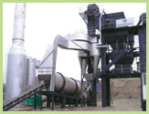 |
| Blower complementary to pitch stirring equipment |
| |
| |
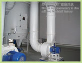 |
| Blower complementary to rice mill and feedstuff factory |
| |
| |
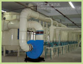 |
| Blower complementary to flour mill |
| |
|